
![]()
LINC2 FILTER – From Traditional Single-ended Filter Design to New
Differential Microwave Filters!
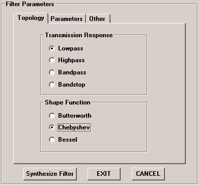
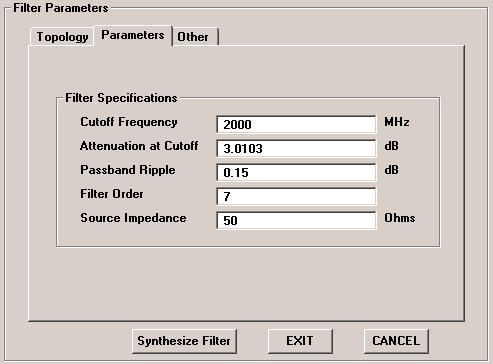
Below is an example of a balanced 7th order distributed Chebyshev lowpass filter designed with LINC2 FILTER.
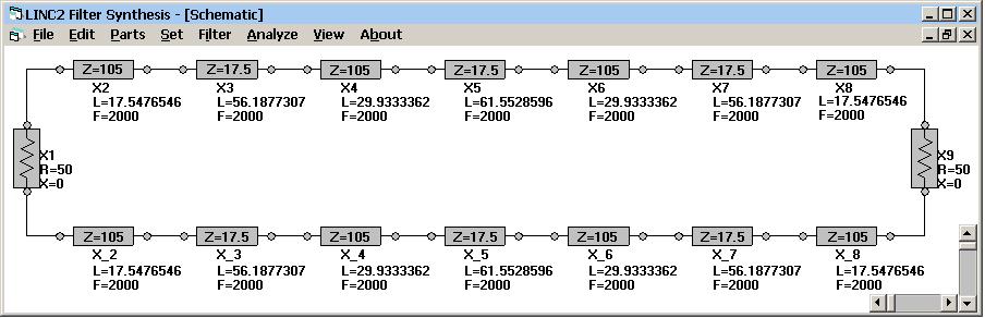
Click Synthesize Filter to generate the differential distributed 7th order Chebyshev lowpass filter (below).
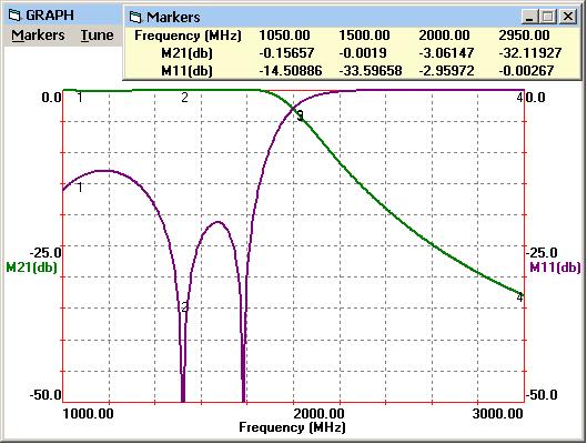
Click Analyze to see the simulation results below. The 3 dB cutoff is
at 2000 MHz as specified.
Select Transmission Line | Convert T-Lines To...| Microstrip from the Parts menu to automatically convert all lines to microstrip (below).
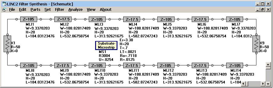
Now the schematic displays all physical dimensions for laying out the filter on a circuit board (graphical representation below).
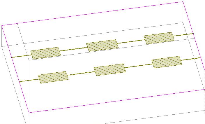
A simulation run on the schematic with physical (microstrip) transmission lines is shown below.
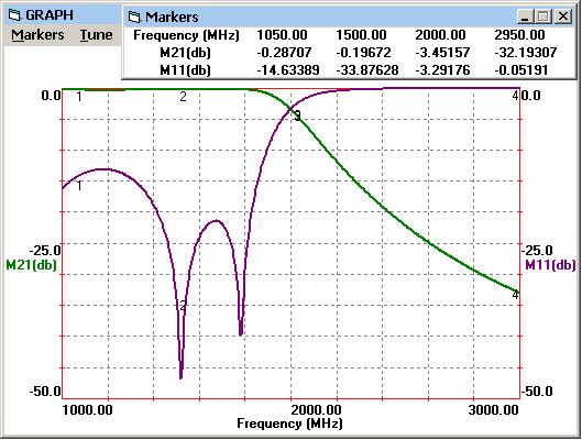
The simulation results from the microstrip filter agree closely with the ideal (electrical TL) filter (above).
Less than 0.5 dB of additional insertion loss is indicated at 2 GHz.
The lowpass frequency response is plotted above for log magnitude of S21 (M21 in dB on left axis).
The input return loss, M11 = 20 Log(S11), is shown plotted against the right axis.
![]()
Click here to order (then click the
credit card icon)à Order LINC2 Pro
Click here to see LINC2 balanced filter designè
LINC2 Differential Filter
Click here to see LINC2 single-ended filter designè LINC2 Single-ended Filter
[RETURN]